Simulating Arduino Projects in Proteus 8: A Beginner's Step-by-Step Guide
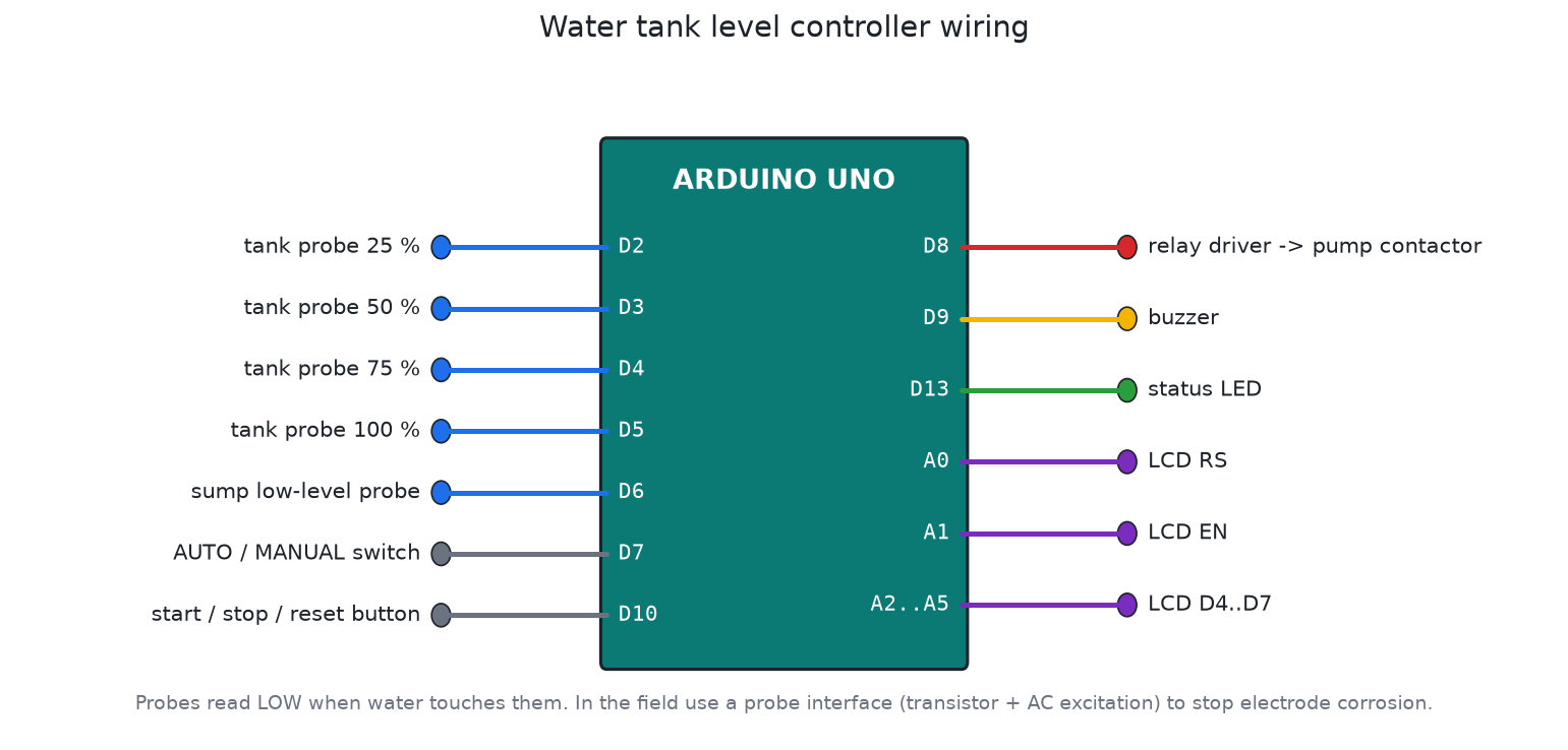
Building a circuit on a breadboard is the best way to learn, but it is also the slowest way to find a mistake. A wrong pin, a missing pull-up resistor or a bug in a timer can cost an evening with a multimeter. Proteus lets you run your actual Arduino firmware against a drawn schematic, so most of those mistakes show up on screen before you touch a soldering iron.
This guide walks through the full process with the Arduino Uno, using the same workflow behind the Proteus projects on this site.
What you need
- Proteus 8 from Labcenter Electronics. Version 8.9 and later include Arduino boards in the library. The free demo can run simulations but cannot save designs.
- Arduino IDE (1.8 or 2.x) to compile your sketch.
- A sketch that already compiles without errors.
Proteus does not compile Arduino code for you in the normal workflow. It runs the compiled machine code, the same HEX file you would upload to a real board.
Step 1: Export the compiled HEX file
In the Arduino IDE, select Tools > Board > Arduino Uno, then choose Sketch > Export Compiled Binary. The IDE writes a .hex file into the sketch folder (or into a build subfolder in IDE 2.x).
You will usually see two files. Use the one without with_bootloader in its name. Proteus loads the program directly into flash, so the bootloader is not needed.
Step 2: Draw the circuit
- Create a new project, schematic only.
- Press P to open the part picker and search for
ARDUINO UNO. If it is missing, your Proteus version is too old or the Arduino library is not installed. - Add the rest of the parts: LEDs with series resistors, buttons, an
LM016Lfor a 16x2 LCD, and so on. - Wire everything as you would on the bench. Ground and power terminals come from the Terminals mode on the left toolbar.
A common beginner mistake is leaving inputs floating. If your sketch uses INPUT_PULLUP, a button only needs to connect the pin to ground. With plain INPUT, add a 10 kΩ resistor yourself or the pin will read random values in simulation, just like on a real board.
Step 3: Load the program into the board
Double-click the Arduino Uno and set:
| Property | Value |
|---|---|
| Program File | the .hex you exported |
| Clock Frequency | 16 MHz |
The clock matters. If it is wrong, delay(1000) will not take one second and serial output will be garbage because the baud rate is off.
Step 4: Run and debug
Press the play button at the bottom left. Pins that are high turn red and low pins turn blue, which makes it easy to follow logic.
For serial output, add a Virtual Terminal from the Instruments mode and connect its RXD to the Arduino's TX pin (D1). Set the terminal to the same baud rate as Serial.begin(). Printing state changes from your code is still the quickest way to find a logic bug.
The Oscilloscope and Logic Analyser instruments are useful for PWM, timing and communication buses such as I2C and SPI.
Making long timers practical
Real controllers often wait minutes or hours. A water pump controller might wait five minutes before restarting after a dry-run trip. Nobody wants to sit through that in a simulation.
A simple fix is a compile-time speed factor:
#define SIM_SPEEDUP 10   // 1 for the real board
const unsigned long RESTART_DELAY_MS = 300000UL / SIM_SPEEDUP;
Build one HEX for the real board and one with SIM_SPEEDUP set to 10 for demos. Several projects in my Proteus repository ship both builds side by side for this reason.
Common problems and fixes
| Symptom | Likely cause |
|---|---|
| Nothing happens when you press play | Program File not set, or it points to an old HEX |
| Timing is far too fast or slow | Clock frequency is not 16 MHz |
| LCD shows black boxes | Wrong pin mapping in LiquidCrystal, or RW not tied to ground |
| Simulation runs very slowly | Too many animated parts, or a very high PWM frequency |
| Inputs flicker randomly | Floating pins without pull-up or pull-down resistors |
Where simulation stops being enough
Proteus models logic and timing well. It does not tell you that a relay contact will weld under a motor's inrush current, that probe electrodes corrode, or that a long sensor cable picks up noise. Treat a working simulation as proof that your logic is right, then plan the real hardware with proper ratings, isolation and enclosures.
A good next project to try is the water tank level controller. It uses buttons as probes, a relay and an LCD, so it covers most of what this guide explains.