Designing a 5V Regulated Power Supply with the 7805: The Calculations That Matter
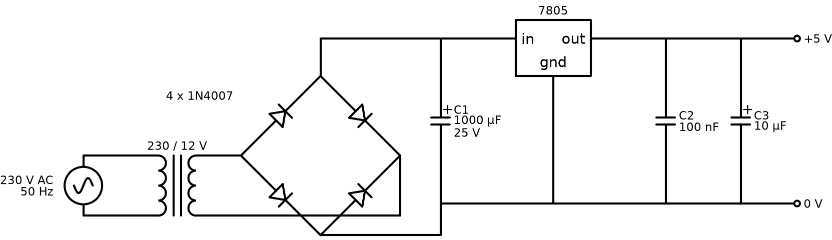
The transformer, bridge rectifier, capacitor and 7805 circuit is usually the first power supply anyone builds. It is also easy to get subtly wrong. The circuit looks fine on paper and gives 5 V with no load, then sags or gets very hot once you connect a real load. The cause is almost always one of three numbers: the filter capacitor, the regulator's dropout voltage, or the heat it has to get rid of.
This post works through those numbers for a supply that delivers 5 V at 500 mA from 230 V, 50 Hz mains.
The circuit in four stages
- Transformer: steps 230 V AC down to a safer, lower AC voltage.
- Bridge rectifier: four diodes turn AC into pulsing DC.
- Filter capacitor: fills in the gaps between pulses.
- 7805 regulator: holds the output at 5 V while its input wanders.
Step 1: How much voltage does the regulator need?
A 7805 is a linear regulator. It needs its input to stay a couple of volts above its output or it stops regulating. This is the dropout voltage, about 2 V for the standard 7805. So the input must never fall below roughly 7 V, not even for a moment at the bottom of the ripple.
Step 2: Transformer and rectifier
Take a 9 V RMS transformer. The peak voltage is:
Vpeak = 9 × √2 ≈ 12.7 V
In a bridge, current always flows through two diodes, each dropping about 0.7 V:
Vpeak (after bridge) ≈ 12.7 − 1.4 = 11.3 V
Transformers also deliver more than their rated voltage at light load and less at full load, and mains voltage itself varies, so leave a margin.
Step 3: Sizing the filter capacitor
Between peaks the capacitor supplies the load current alone and its voltage drops. For a full-wave rectifier on 50 Hz mains, the capacitor is recharged 100 times a second. The peak-to-peak ripple is approximately:
Vripple = I / (2 × f × C)
With 500 mA and a 1000 µF capacitor:
Vripple = 0.5 / (2 × 50 × 0.001) = 5 V
The voltage then dips to 11.3 − 5 = 6.3 V, below the 7 V the 7805 needs. The output will show 100 Hz ripple under load even though it read a perfect 5 V on the bench with nothing connected. This is a very common mistake.
With 2200 µF:
Vripple = 0.5 / (2 × 50 × 0.0022) ≈ 2.3 V
The minimum is now about 9 V, comfortably above dropout. Use a capacitor rated at least 25 V, since the peak is over 11 V and rises further at light load.
| Filter capacitor | Ripple at 500 mA | Lowest input voltage | Regulates? |
|---|---|---|---|
| 1000 µF | 5.0 V | 6.3 V | No |
| 2200 µF | 2.3 V | 9.0 V | Yes |
| 3300 µF | 1.5 V | 9.8 V | Yes, with margin |
Also fit the small capacitors the datasheet asks for: about 0.33 µF on the input and 0.1 µF on the output, placed close to the regulator pins. They keep it stable.
Step 4: Heat, the part people forget
A linear regulator burns off the difference between input and output as heat:
P = (Vin − Vout) × I
The average input here is about 10 V, so:
P ≈ (10 − 5) × 0.5 = 2.5 W
A TO-220 7805 with no heat sink has a thermal resistance from junction to air of roughly 50 to 65 °C/W. At 2.5 W the junction would try to rise 125 °C or more above room temperature. The regulator's thermal shutdown would kick in and the output would cut in and out.
So for 500 mA you need a heat sink. Work backwards: to keep the junction under about 125 °C in a 40 °C room, the whole thermal path must be under (125 − 40) / 2.5 = 34 °C/W. Subtract the regulator's internal junction-to-case resistance (about 5 °C/W) and the thermal pad, and you need a heat sink of roughly 25 °C/W or better.
A lower transformer voltage reduces heat, but only if the ripple trough still stays above 7 V. That trade-off is what the whole design is balancing.
When to use a switching regulator instead
If you need more than about an amp, or you are running from batteries, a buck converter is the better choice. It can be over 85 % efficient where the linear design above is about 50 %. The linear supply still wins on simplicity, low noise and cost for small loads.
See it simulated
The 5 V regulated power supply project has the schematic and PCB layouts in Proteus. Its README notes that the original capacitor values needed fixing, which is exactly the ripple problem described above.