5 V regulated power supply
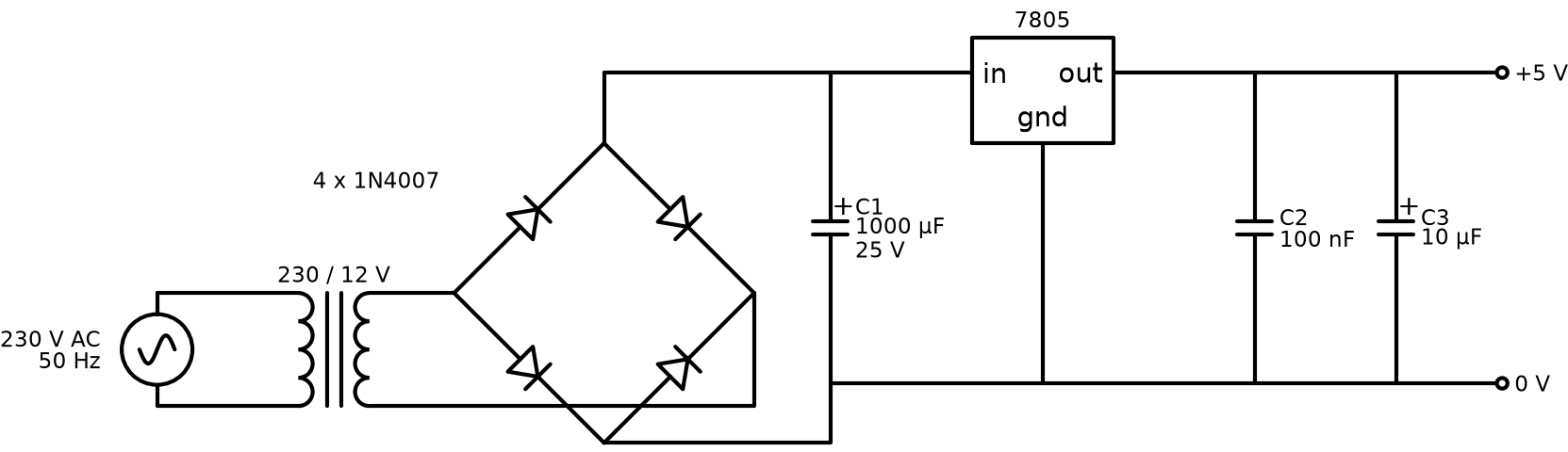
A linear 230 V AC to 5 V DC supply. It has a step-down transformer, a bridge rectifier made from four 1N4007 diodes, a reservoir capacitor and a 7805 regulator. I drew it three times while learning Proteus, so this folder has the simulation version and two PCB versions with the 3D view.
Files
| File | What it is |
|---|---|
proteus/psu-simulation.pdsprj | Schematic only, with instruments for simulation |
proteus/psu-pcb-3d.pdsprj | Same circuit plus PCB layout and 3D view |
proteus/psu-pcb-rev2.pdsprj | Second PCB attempt, with a different capacitor value |
Fix this before building it
When I checked the 2023 files, I found two value mistakes:
- The big polarized capacitor after the bridge is set to 1 nF. That does almost nothing at 100 Hz. The 7805 would see raw pulsing DC and drop out on every half cycle. It should be 1000 µF / 25 V (or 2200 µF for 1 A, see below).
- The small capacitors are 1.5 pF (and 0.015 µF in rev2). The 7805 datasheet asks for about 0.33 µF on the input and 0.1 µF on the output, right at the pins. Use 100 nF ceramics.
To change a value in Proteus, double-click the part, set Capacitance (for example 1000u or 100n) and save. I can't edit the .pdsprj files from Linux, so these fixes still need doing in Proteus. The schematic above already shows the corrected values.
Numbers
With a 12 V RMS secondary:
- Peak after the bridge: 12 × 1.414 − 2 × 0.7 ≈ 15.6 V
- Ripple at load current I: ΔV ≈ I / (2 × 50 Hz × C)
- 0.5 A with 1000 µF: ΔV ≈ 5 V, so the valley is about 10.6 V. That's fine, because the 7805 needs about 7 V in.
- 1 A with 1000 µF: ΔV ≈ 10 V, so the valley is about 5.6 V and the output drops out. Use 2200 µF for 1 A (ΔV ≈ 4.5 V).
- 7805 heat at 0.5 A: (15.6 − 5) × 0.5 ≈ 5 W. That needs a real heatsink. A TO-220 on its own will go into thermal shutdown.
If you need more than about 300 mA, a buck converter module (LM2596 or MP1584) runs cold and wastes far less power. I kept the linear design here because it's the classic first PSU and it simulates well.
Running it in Proteus
- Open
proteus/psu-simulation.pdsprj. - Fix the capacitor values as described above.
- Run the simulation. Put the oscilloscope on the bridge output and the 5 V rail to see the ripple, and how the regulator removes it.
- For the PCB, open
psu-pcb-3d.pdsprj, go to the PCB Layout tab, then 3D Visualizer.
Safety
The primary side carries mains voltage. Use a fused IEC inlet (500 mA slow-blow), insulate the transformer primary, earth any metal enclosure, and never probe the primary with a normal oscilloscope ground clip.