Earthing System Design for Buildings and Industrial Plants in Nepal
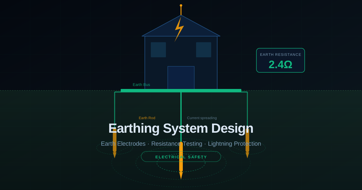
Why Earthing Is the Most Critical Safety System
Earthing (also called grounding) is arguably the single most important safety system in any electrical installation. Its primary function is to provide a low-impedance return path for fault current, causing the protective device (fuse or circuit breaker) to operate quickly and disconnect the supply before a person can receive a fatal shock. A poorly designed earthing system can allow dangerous touch voltages to persist for seconds u2014 long enough to be fatal.
Nepalu2019s Soil Conditions and Their Impact
Nepalu2019s varied geology creates significantly different earthing challenges across regions. The Teraiu2019s moist alluvial soil typically gives very low soil resistivity (10u2013100 u03a9u00b7m), making earth electrodes easy to install with low resistance. Kathmandu Valleyu2019s clay and silt gives moderate resistivity (50u2013200 u03a9u00b7m). The hilly and mountain regions with rocky terrain can have extremely high resistivity (1,000u20135,000 u03a9u00b7m or more), requiring special techniques including chemical earthing compounds or deep-driven rods into water-bearing strata.
Electrode Types and When to Use Them
- Plate electrodes (600mm u00d7 600mm copper or GI): Used where space is available and soil is workable. Buried at minimum 3m depth with good contact with moist soil.
- Rod electrodes (copper-bonded steel, 16mm u00d7 3m): Most common type. Multiple rods in parallel for low-resistance targets. Minimum spacing equal to rod length.
- Chemical earthing electrodes: Backfilled with bentonite or proprietary compounds. Effective in rocky terrain. Maintains low resistance even in dry seasons.
- Ring earth electrode: Bare copper conductor buried around the building perimeter. Combined with vertical rods at intervals. Best for large buildings and industrial plants.
Target Resistance Values
Target earth resistance depends on the installation type. General purpose building earthing: below 10 ohms. Substation main earth grid: below 1 ohm. Electronic equipment and data centres: below 1 ohm. Lightning protection earth: below 10 ohms per electrode. Sensitive medical equipment in hospitals: below 0.2 ohms. These values must be achieved under worst-case dry season conditions, not just during monsoon when soil is moist.
Earth Resistance Testing Method
The standard fall-of-potential method uses a dedicated earth tester (NOT a multimeter). Three terminals connect to the electrode under test (E), a current electrode (C) driven 40 metres away, and a potential electrode (P) driven 20 metres away between E and C. The tester passes a small AC test current and measures the voltage drop to calculate resistance. Measurements must be taken at different P electrode positions to confirm a stable reading u2014 if results vary widely with P position, the electrode spacing is too small.
Common Earthing Mistakes in Nepal
- Using galvanised iron (GI) pipe as earth electrode: corrodes rapidly in Nepalu2019s acidic soils, giving false low readings initially but high resistance within 2u20133 years
- Measuring earth resistance only during monsoon season: gives optimistic results; always test in dry season
- Connecting neutral and earth at multiple points (creating neutral current on earth conductors)
- Using undersized earthing conductors: minimum 16mmu00b2 copper for LV systems, sized for full fault current
- Not bonding all metallic structures together: creates potential differences that cause shock risk
Lightning Protection Integration
Lightning protection earthing must be integrated with the buildingu2019s electrical earthing system u2014 not kept separate as sometimes incorrectly specified. Separate systems allow dangerous voltage differences to develop between them during a lightning strike. The combined system must achieve below 10 ohms. Surge Protection Devices (SPDs) at the MV/LV transformer secondary and at the main distribution board are essential in Nepalu2019s lightning-prone mountain regions.