Earthing and Grounding in Electrical Systems, Why It Saves Lives
I still remember the first time a senior engineer stopped me mid-task on site and asked, "Have you checked the earth resistance today?" I hadn't. He didn't lecture me — he just walked over to the earth pit, ran the test himself, and showed me the reading was drifting above 5 ohms. Then he explained, calmly, that a bad earth connection is the difference between a fault tripping safely and someone getting killed. That conversation has stayed with me through every project since.
Earthing is one of those subjects that looks boring on paper and becomes deadly serious the moment something goes wrong. Here's what I've learned about it from actual fieldwork, not just textbooks.
What Earthing Actually Does
At its core, earthing gives fault current somewhere safe to go. Without a proper earth path, a live wire touching a metal enclosure doesn't trip anything — it just sits there, energizing the case, waiting for someone to touch it. With a good earth connection, that fault current finds a low-resistance path back to source, the protective device sees the surge, and the circuit trips before anyone gets hurt.
It sounds simple. In practice, getting it right on a real site — especially in Nepal's varied soil conditions — takes more care than most people expect.
The Common Systems You'll Run Into
IEC 60364 defines a few standard earthing arrangements, and you'll see different ones depending on where you're working:
TN-S — separate neutral and protective earth conductors all the way from the source. Clean, predictable, but needs more cabling.
TN-C-S — combined neutral-earth conductor for part of the run, separated near the point of use. Common in a lot of Nepali distribution networks because it's cheaper to install.
TT — no direct metallic earth connection to the source at all; each installation has its own local earth electrode. You'll see this a lot in rural areas where the utility doesn't provide a reliable earth reference.
IT — the system is deliberately isolated from earth, or connected through a high impedance. Rare in general use, but you'll find it in some industrial and medical setups where continuity of supply during a first fault matters more than immediate disconnection.
Knowing which system you're dealing with changes everything about how you size protective devices and where you place your earth electrodes.
Installing an Earth Electrode Properly
On one substation job, we had a spot where the soil was dry, rocky, and stubbornly high-resistance no matter what we tried. Here's roughly what worked, and what didn't.
Rod electrodes are the default — copper-bonded steel rods driven vertically into the ground, usually in a series connected together to reduce overall resistance. Depth matters more than most people realize; moisture content increases with depth, and a rod driven 3 meters down will almost always outperform one at 1.5 meters in the same soil.
Plate electrodes work better in shallow, rocky ground where driving a rod deep isn't practical. You bury a horizontal copper or galvanized iron plate, and it spreads its resistance area sideways instead of down.
Chemical earthing — using conductive backfill compounds around the electrode — genuinely helped us on that dry site. It retains moisture around the rod and gradually improves resistance over the following weeks as it settles into the surrounding soil.
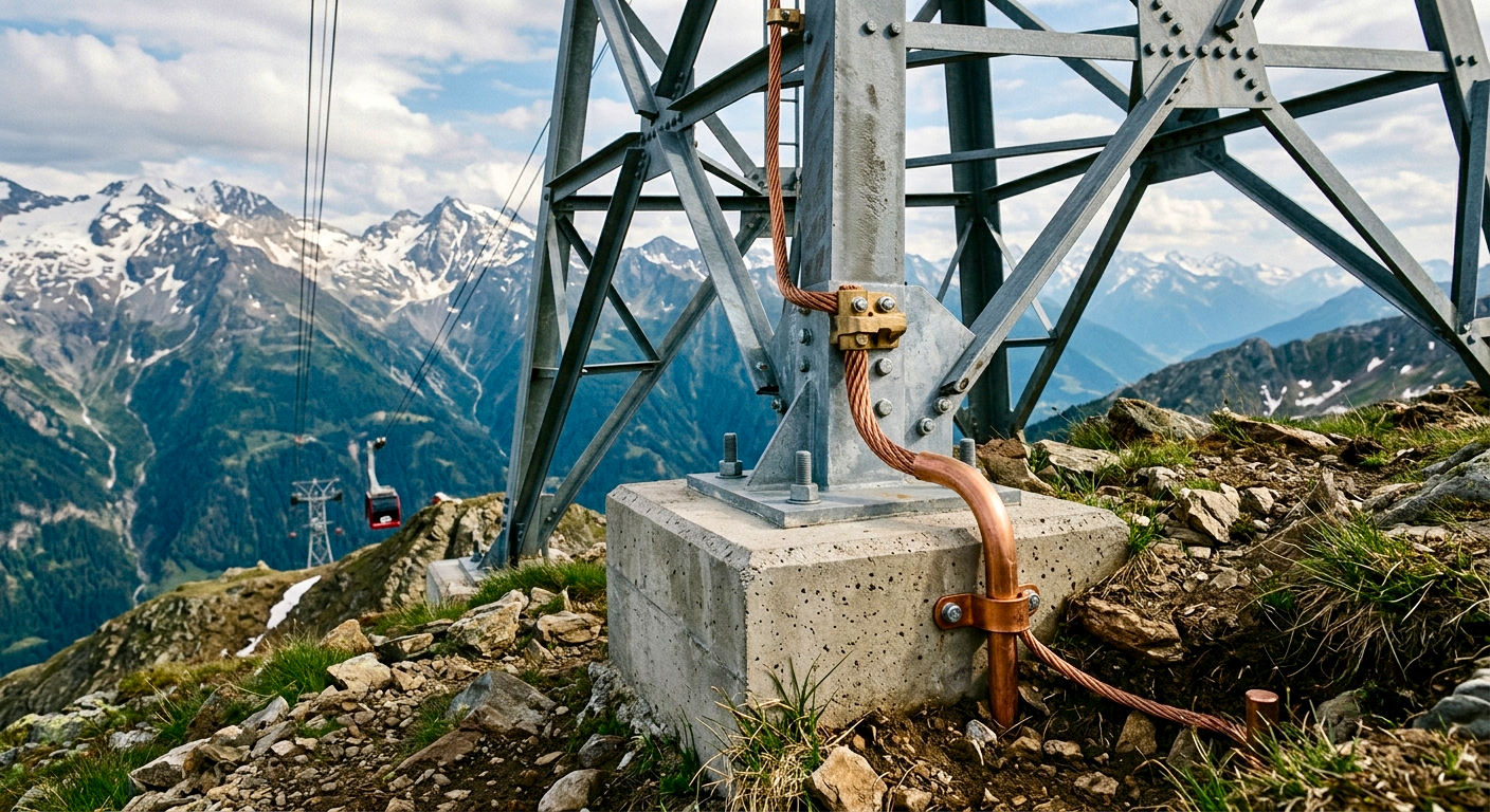
Whatever electrode type you use, bond it properly, protect the connection point from corrosion, and label the test point clearly. I've seen earth pits get built over or paved over within a year because nobody marked them — and then nobody could test them again.
Testing: The Fall-of-Potential Methods
This is the test my senior colleague ran that day, and it's still the standard for verifying earth resistance in the field.
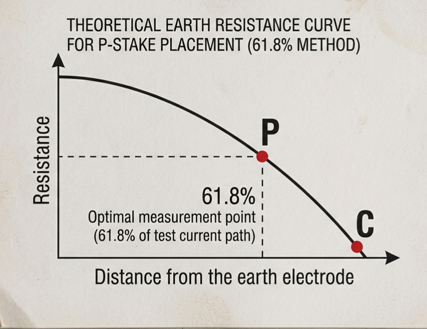
You need three electrodes: the one you're testing (C1), and two auxiliary spikes driven into the ground at increasing distances — typically one at around 5 times the length of your earth rod, and another beyond that. You inject a known current between the test electrode and the far auxiliary spike, then measure the voltage drop between the test electrode and the middle spike at various distances. Plot the readings, and you're looking for a flat "plateau" in the curve — that plateau value is your actual earth resistance.
If your readings keep climbing instead of leveling off, your auxiliary spikes are too close together and you need to space them further apart before the test means anything.
For most low-voltage installations in Nepal, NEA and general good practice look for something below 5 ohms for a single earth electrode, though this varies by application — substations and lightning protection systems often demand much lower.
Mistakes I've Actually Seen on Site
Undersized earth conductors. A tiny earth wire on a large fault-current system means the conductor itself can fail or overheat before it does its job.
Painted or corroded connection points. I once found an earth clamp that had been painted over during a repaint of the panel — completely insulating it. Nobody had checked it in years.
Earth and neutral bonded in the wrong place. In a TN-C-S system, that bond needs to happen at a specific, defined point — get it wrong and you can end up with stray currents flowing where they shouldn't, sometimes through pipework or building steel.
No periodic retesting. Soil resistance changes with the seasons — dry season readings can be double what you'd get in monsoon. A system tested once during installation and never again is a system nobody can vouch for years later.
Why This Matters More Than It Seems
Earthing rarely gets the attention it deserves because when it works, nothing happens — no shocks, no fires, no dramatic failures. It's invisible engineering. But when it's done badly, the consequences are immediate and severe, and by the time you find out, it's usually too late to matter.
Every time I'm on site now, checking the earth pit isn't a formality for me anymore. It's the first thing I look at.
If you're working on an earthing or protection system in Nepal and want a second opinion, feel free to reach out through my contact page.