Small Hydropower Electrical Systems: Design Considerations for Nepal
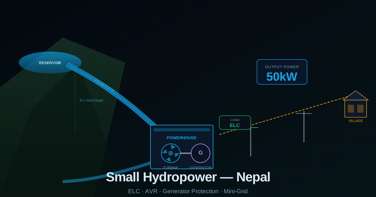
Nepalu2019s Small Hydropower Opportunity
Nepal has an estimated 83,000 MW of technically feasible hydropower potential, of which small and micro hydro (below 10 MW and below 100 kW respectively) plays a vital role in electrifying remote communities where grid extension is not economically viable. As an electrical engineer who has worked near hydropower infrastructure, I want to outline the key electrical system considerations for small hydro projects ranging from 5 kW village schemes to 1 MW run-of-river installations.
Generator Selection: Synchronous vs Induction
Small hydro generators are almost always synchronous generators (alternators) for isolated grid applications where the generator must control both voltage and frequency independently. Induction generators are cheaper but require a capacitor bank for reactive power supply and cannot operate in isolation from a grid u2014 they are only suitable for grid-connected systems where the main grid controls voltage and frequency. For remote Nepal villages, synchronous generators are the correct choice.
Electronic Load Controller (ELC) u2014 Nepalu2019s Key Technology
The Electronic Load Controller (ELC) is the most important piece of electrical equipment in a micro-hydro system. The turbine-generator set runs at constant power output because the penstock (water pipe) flow is fixed. When consumer load decreases, the ELC automatically diverts excess power to a ballast (dump) load u2014 typically electric water heaters or space heaters. This maintains constant generator frequency and voltage regardless of how much the communityu2019s actual consumption varies. Without the ELC, the generator frequency would change with every load switch u2014 damaging sensitive electronics and causing lights to flicker.
Automatic Voltage Regulator (AVR) Function
The AVR continuously monitors generator terminal voltage and adjusts the excitation current to the field winding to maintain a stable output voltage regardless of load changes. Modern digital AVRs can maintain voltage within u00b11% of setpoint. Key AVR settings: voltage setpoint (typically 400V u00b12%), droop setting (for parallel operation with other generators), stability gain, and under-frequency rollback (reduces voltage proportionally when frequency drops u2014 protects the generator under overload conditions).
Protection for Small Hydro Generators
- Over/under voltage protection: Trips generator if terminal voltage departs more than 10u201315% from nominal for longer than 2 seconds.
- Over/under frequency protection: Trips if frequency departs more than 5% from 50 Hz. Indicates loss of load control or ELC failure.
- Overcurrent protection: Set at 110u2013120% of rated current. Time-delayed to allow starting of motors connected to the mini-grid.
- Differential protection: For generators above 100 kW u2014 compares current entering and leaving the generator windings. Operates within 1 cycle on internal winding faults.
- Earth fault protection: Stator earth fault detection using neutral displacement relay or sensitive earth fault relay on generator neutral.
Distribution to the Village Mini-Grid
Small hydro generator output (typically 400V three-phase) is stepped up to 11 kV for distribution over distances greater than 500 metres to minimise cable losses. A distribution transformer at the village steps back down to 400/230V for household use. The distribution network design must ensure: maximum voltage drop of 5% at the furthest consumer under full load, adequate cable ampacity for fault current, weatherproof pole-mounted equipment suitable for Nepalu2019s monsoon climate, and clearly labelled isolation points for maintenance safety.
Power Quality Challenges in Micro-Hydro Systems
Village micro-hydro systems face unique power quality challenges. Single-phase dominant loads (households using 230V appliances) create phase imbalance. Inrush of motor loads such as grain mills creates voltage dips. Harmonic loads from CFL/LED lighting and phone chargers create waveform distortion. The ELC ballast load itself can introduce flicker if switched in large steps. Modern ELC designs use thyristor phase control or pulse-width modulation to switch the ballast load continuously rather than in steps, eliminating this flicker issue.