Short Circuit Analysis: How to Calculate Fault Levels and Select Protection Devices
Why Every Electrical Engineer Must Understand Short Circuit Analysis
Short circuit analysis is the foundation of electrical protection design. Without knowing the maximum fault current that can flow at each point in a distribution system, it is impossible to correctly select circuit breakers, fuses, cable sizes, and busbar ratings. Undersized equipment can be destroyed in a fault u2014 or worse, can fail to interrupt the fault current, allowing an arc flash or fire to develop.
Types of Short Circuit Faults
- Three-phase symmetrical fault (L-L-L): All three phases connect together. Produces the highest fault current u2014 used for equipment rating selection.
- Single line-to-ground fault (L-G): One phase contacts earth. Most common fault type (70u201380% of all faults). Magnitude depends on system earthing method.
- Line-to-line fault (L-L): Two phases connect together. Fault current approximately 86% of three-phase fault level.
- Double line-to-ground fault (L-L-G): Two phases contact earth simultaneously. Complex to analyse, intermediate fault current levels.
Calculating Three-Phase Fault Current
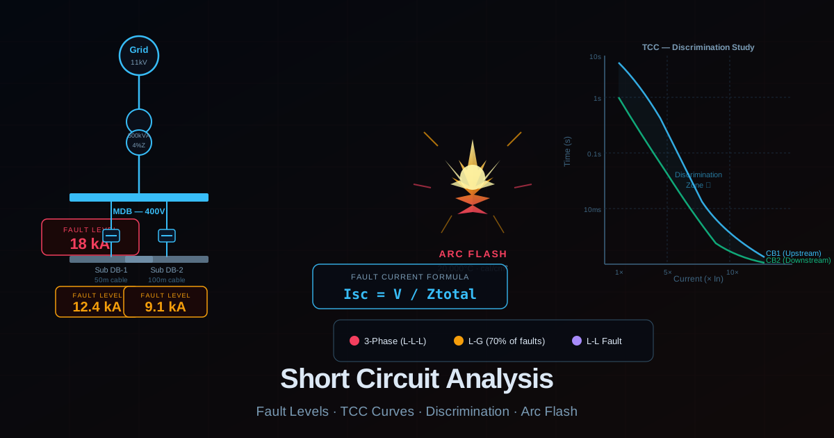
The maximum three-phase fault current at any point equals the supply voltage divided by the total impedance to that point: Isc = V / (Z_source + Z_transformer + Z_cable). In per-unit system, this becomes: Isc = 1 / Z_total (pu) u00d7 Ibase. For a practical example: a 400V distribution board fed by a 500 kVA transformer with 4% impedance. The transformer base current is 500,000 / (1.732 u00d7 400) = 722A. Maximum fault current at transformer secondary terminals = 722 / 0.04 = 18,050A (18 kA). This is the minimum rating required for the main distribution board incomer circuit breaker.
Impedance of Cables Reduces Fault Level
As distance from the transformer increases, cable impedance adds to the total circuit impedance, reducing fault current. A 50 metre run of 95mmu00b2 copper cable has approximately 0.011 ohm resistance and 0.005 ohm reactance per phase. This adds to the transformer impedance. By the time you reach a distribution board 50 metres away, the fault level may have dropped from 18 kA at the transformer to 12u201314 kA. This is why discrimination studies must analyse each level of the distribution hierarchy separately.
Protection Discrimination (Selectivity)
Discrimination means ensuring that when a fault occurs, only the protective device closest to the fault operates u2014 leaving all other circuits unaffected. Poor discrimination causes entire buildings or factory sections to go dark when only one circuit faults. Achieving discrimination requires the downstream device (closer to load) to operate faster and at lower current than the upstream device at all possible fault current levels. Time-current characteristic curves (TCC curves) from the device manufacturer must be plotted on the same graph and checked for adequate separation.
Arc Flash Hazard
When a short circuit develops in air between conductors or between a conductor and earth, it may not immediately form a solid metal-to-metal connection. Instead, an electric arc forms. Arcing fault current is typically 38u201385% of bolted fault current but the energy released is enormous u2014 arc temperatures exceed 20,000u00b0C. Engineers and technicians working near energised equipment must wear appropriate arc flash PPE rated for the incident energy level calculated from the fault analysis. This calculation is increasingly required by international safety standards.
Practical Tools for Fault Analysis
Manual calculations using the per-unit method work well for simple radial systems. For complex industrial plants with multiple transformers, generators, and motor contributions, software tools such as ETAP, SKM PowerTools, or DIgSILENT PowerFactory are used. These produce full fault level reports, discrimination studies, and arc flash calculations that meet international standard requirements for as-built documentation.