DC power and energy meter with protection
For solar panels, batteries and DC supplies. It shows volts, amps, watts and watt-hours on a 16x2 LCD and logs CSV over USB. It also switches the load off on over-voltage, over-current, a short circuit or a flat battery.
Specs
| Voltage | 0 to 27.7 V, using a 100k / 22k divider into A0 |
| Current | ±5 A, using an ACS712-05B into A1 (185 mV/A). Swap in the 20 A or 30 A version by changing one constant. |
| Readings | 5 per second, each the average of 64 ADC samples |
| Current zero | Measured automatically at power-on while the load is still disconnected |
| Energy | Integrated every reading. Saved to EEPROM every 10 min across 16 rotating slots, which makes the EEPROM last decades instead of about a year |
Protection (the relay on D8 connects the load):
| Condition | Action |
|---|---|
| > 26.0 V for 0.5 s | Trip, latched |
| > 4.5 A for 0.2 s | Trip, latched |
| ACS712 at full scale (dead short) | Trip immediately, latched |
| < 10.5 V for 3 s (flat 12 V battery) | Disconnect, then reconnect by itself after 10 s above 12.0 V |
A short press on the button clears a latched trip, but only once the cause has gone. Holding it for 3 s clears the energy counter.
The load is never connected at power-on until the first reading shows a sane voltage.
CSV log
At 9600 baud it prints a header, then one line per second, ready for Excel or Python:
DATA,seconds,volts,amps,watts,watt_hours,state
DATA,12,12.01,2.008,24.11,0.063,ON
Files
| File | What it is |
|---|---|
firmware/dc_power_meter/dc_power_meter.ino | Firmware |
firmware/build/dc_power_meter.hex | Build (real time, no scaling needed) |
test/sim_test.c | Automatic bench test (simavr) |
Building it in Proteus
- Add
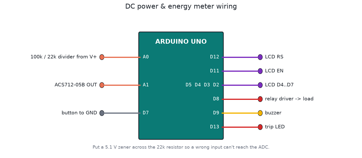
ARDUINO UNO,LM016L,RES100k and 22k,POT-HG(to stand in for the ACS712 output),RELAY+ NPN driver + diode,BUTTON,BUZZER,LED-RED, and aBATTERYor variable DC source for the input. - LCD wiring is the classic Arduino example: RS = D12, E = D11, D4 to D7 = D5, D4, D3, D2.
- Divider: input + to 100k, 100k to A0, A0 through 22k to GND.
- Current: put the POT-HG wiper on A1, between 0 and 5 V. 2.5 V means 0 A, and each extra 185 mV means 1 A. Leave it at 2.5 V while the simulation starts, because that's when the meter learns its zero.
- Set the Arduino's Program File to
firmware/build/dc_power_meter.hex, then run it and play with the input voltage and the pot.
Save it as proteus/dc-power-meter.pdsprj and commit it.
Calibration
Measure the Uno's 5 V pin with a good multimeter and put the value in VREF. Measure the two divider resistors and update DIVIDER_RATIO. That's usually enough for ±1 % on voltage. For current, compare against a clamp meter at about 2 A and adjust ACS_MV_PER_A if needed.
Safety
- Put a 5.1 V zener (with a 1k series resistor) on A0, so a wrong connection can't kill the ADC.
- The ACS712 is isolated, but its PCB tracks aren't rated for mains. This meter is for low-voltage DC only.
- Fuse the load path to match the relay and the wiring.
Testing
The test checks the 12.0 V / 2.00 A / 24 W readings and the Wh integration, plus over-current (with the short-overload grace time), the latch and reset, short circuit, over-voltage with a refused reset, low-voltage disconnect with hysteresis and auto-reconnect, and clearing the energy counter.