PLC Programming for Motor Control: Step-by-Step Tutorial

Programmable Logic Controllers are at the heart of modern industrial motor control. This tutorial walks through a basic motor start/stop control ladder logic program using Siemens S7-1200.Hardware SetupYou will need TIA Portal v16+, a Siemens S7-1200 CPU 1214C, a 3-phase induction motor, a contactor (e.g., Siemens 3RT2), and a thermal overload relay.Ladder Logic Design</
Ladder Logic Design
The ladder logic for a basic motor start/stop circuit mirrors the classic hardwired control schematic, translated into the PLC environment. In TIA Portal, you'll work in the LAD (Ladder) editor within your S7-1200 program block.
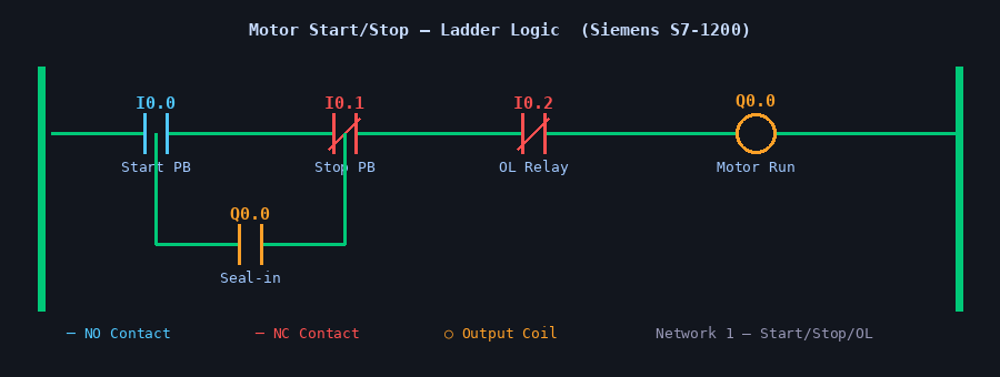
Network 1 – Start/Stop/Overload Logic
The first network implements the fundamental seal-in circuit. Place a normally-open contact for your Start pushbutton (e.g., %I0.0) in series with a normally-closed contact for your Stop pushbutton (%I0.1) and a normally-closed contact for the thermal overload relay feedback (%I0.2). The output coil drives the Motor Run bit (%Q0.0), which energises the contactor coil.
To create the seal-in (latching) behaviour, add a parallel branch with a normally-open contact of %Q0.0 in parallel with the Start contact. This holds the motor running even after the operator releases the Start button.
Network 2 – Fault Indicator
Add a second network to illuminate a fault lamp (%Q0.1) whenever the overload relay trips. Use a normally-closed contact of %I0.2 feeding the output coil %Q0.1. This gives the operator a clear visual indication at the panel without any additional hardware relay.
I/O Tag Table
Before downloading, define your tags in the PLC tag table for readability and maintainability:
| Tag Name | Address | Data Type | Comment |
|---|---|---|---|
| Start_PB | %I0.0 | Bool | Start pushbutton (NO) |
| Stop_PB | %I0.1 | Bool | Stop pushbutton (NC) |
| OL_Relay | %I0.2 | Bool | Overload relay (NC) |
| Motor_Run | %Q0.0 | Bool | Contactor coil output |
| Fault_Lamp | %Q0.1 | Bool | Fault indicator lamp |
Downloading and Testing
Compile your program in TIA Portal (Ctrl+B) and check that zero errors appear in the output window. Connect to the S7-1200 via Ethernet, go to Online → Download to Device, and select your CPU. Once downloaded, switch the CPU to RUN mode.
Use the Watch Table to monitor your I/O bits in real time. Force %I0.0 to TRUE momentarily and confirm that %Q0.0 latches. Then force %I0.1 to FALSE (simulating a pressed NC stop button) and verify the motor output drops. Finally, simulate an overload trip by forcing %I0.2 to FALSE and confirm both %Q0.0 de-energises and %Q0.1 illuminates.
Safety Considerations
Always ensure the thermal overload relay is wired in the hardwired control circuit as well, not solely as a PLC input. The PLC program is a control layer — it does not replace the physical protection chain. For any installation that falls under IEC 62061 or ISO 13849, a formal safety assessment of the complete circuit is mandatory before commissioning.