Electrical Safety Equipment & Drive Systems in Modern Cable Cars
A technical deep-dive into VFDs, safety relays, overspeed governors, emergency braking circuits, and the safety-function chain that keeps aerial ropeways operating without incident, written from an electrical engineer's perspective.
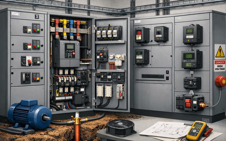
A cable car drive station is, at its core, a carefully orchestrated electrical system. The mechanics get the glory, the ropes, the grips, the bull wheels but it's the electrical engineering underneath that keeps 200 passengers suspended safely over a mountain valley. This post walks through every major electrical subsystem: from the incoming 3-phase supply down to the safety relay NC loop that triggers the rope brake if anything goes wrong.
Standards referenced: EN 12929, EN 13223, IEC 62061 (SIL), IEC 61508, CSA Z98.
who this is for ?
Electrical engineers working on ropeway drive systems, commissioning engineers on Doppelmayr / Leitner / Poma installations, and EE students specialising in industrial drive and safety systems.
1. Power Supply Architecture
The drive station is typically fed from a dedicated 11kV or 33kV medium-voltage spur, stepped down through a dedicated station transformer. No cable car drive station should share a transformer with other loads — voltage sags during motor starting or regenerative braking transients can interfere with the safety PLC's power supply.
Transformer specification
The drive transformer is typically rated at 1.5–2× the drive motor nameplate kVA to accommodate starting transient peaks. A Dyn11 vector group is standard — it eliminates triplen harmonics from the delta winding and prevents zero-sequence currents from the motor-side VFD PWM from reaching the utility. Forced-air or ONAN cooling depending on altitude (at 3,000 m ASL, derating of 10–15% applies).