Battery Energy Storage Systems (BESS): Electrical Architecture and Protection Design
As renewable energy adoption continues to grow worldwide, maintaining a stable electrical grid has become increasingly challenging. Solar and wind energy are clean and sustainable, but they are also intermittent. This is where Battery Energy Storage Systems (BESS) play a crucial role.
A well-designed BESS stores electrical energy during periods of low demand or excess renewable generation and releases it when needed. However, building a reliable battery storage system requires much more than connecting batteries together. Proper electrical architecture and protection design are essential for ensuring safety, performance, and long-term reliability.
In this article, we'll explore the complete electrical architecture of a Battery Energy Storage System and the protection methods used in modern installations.
What is a Battery Energy Storage System (BESS)?
A Battery Energy Storage System is a combination of batteries, power electronics, monitoring equipment, and protection devices that stores electrical energy for later use.
BESS applications include:
- Renewable energy integration
- Peak shaving
- Load shifting
- Frequency regulation
- Emergency backup power
- Microgrids
- Electric vehicle charging support
- Industrial power management
Whether installed in homes or utility-scale power plants, every BESS follows a similar electrical architecture.
Main Components of a BESS
1. Battery Cells
Battery cells are the smallest energy storage units.
Common battery technologies include:
- Lithium Iron Phosphate (LFP)
- Lithium Nickel Manganese Cobalt (NMC)
- Sodium-ion batteries
- Lead-acid batteries (older systems)
Modern utility-scale systems primarily use lithium-ion technology because of its high efficiency and long cycle life.
2. Battery Modules
Multiple cells are connected together to create battery modules.
Each module typically contains:
- Battery cells
- Temperature sensors
- Voltage monitoring
- Cell balancing circuits
Modules make maintenance easier and improve system reliability.
3. Battery Racks
Several modules are installed inside battery racks.
A rack includes:
- DC busbars
- Isolation switches
- Rack monitoring
- Protection devices
Multiple racks form one battery bank.
4. Battery Management System (BMS)
The Battery Management System is often considered the "brain" of a BESS.
Its primary functions include:
- Cell voltage monitoring
- Temperature monitoring
- Current monitoring
- State of Charge (SOC) calculation
- State of Health (SOH) estimation
- Cell balancing
- Fault detection
- Emergency shutdown
Without an effective BMS, battery life decreases rapidly, and safety risks increase.
5. Power Conversion System (PCS)
The Power Conversion System converts:
- DC from batteries → AC for the grid
- AC from the grid → DC for charging
The PCS consists of:
- Bidirectional inverter
- DC/DC converter (if required)
- Grid synchronization controls
- Power quality management
6. Transformer
Most large BESS installations connect to medium-voltage networks.
The transformer:
- Steps inverter voltage up
- Provides electrical isolation
- Matches utility voltage requirements
7. Energy Management System (EMS)
The EMS coordinates the entire storage system.
Responsibilities include:
- Charge scheduling
- Discharge scheduling
- Peak demand reduction
- Renewable energy optimization
- Grid communication
- Performance reporting
Typical Electrical Architecture
A simplified electrical flow is shown below:
Grid
 │
Transformer
 │
Switchgear
 │
PCS (Bidirectional Inverter)
 │
DC Bus
 │
Battery Racks
 │
Battery Modules
 │
Battery Cells
The EMS supervises the complete system, while the BMS monitors every battery cell.
Electrical Protection Design
Protection is one of the most important aspects of a Battery Energy Storage System.
A single fault can damage expensive equipment or create significant safety hazards.
Below are the major protection systems used in modern BESS installations.
1. Overcurrent Protection
Overcurrent may occur because of:
- Internal faults
- Short circuits
- Equipment failure
Protection devices include:
- DC fuses
- Circuit breakers
- Electronic current monitoring
- Fast disconnect switches
2. Overvoltage Protection
Battery voltage exceeding safe limits can damage cells.
Protection methods include:
- BMS voltage monitoring
- Surge protection devices
- Controlled charging algorithms
- Inverter protection
3. Undervoltage Protection
Deep discharge permanently reduces battery life.
The BMS disconnects the battery before voltage falls below safe operating limits.
4. Short Circuit Protection
Short circuits can produce extremely high fault currents.
Protection devices include:
- High-speed DC breakers
- Current-limiting fuses
- Fault detection relays
- Arc flash mitigation systems
5. Thermal Protection
Battery temperature has a direct impact on performance and safety.
Monitoring includes:
- Cell temperature
- Module temperature
- Rack temperature
- Ambient temperature
Cooling methods include:
- Air cooling
- Liquid cooling
- HVAC systems
- Refrigeration systems
6. Ground Fault Protection
Ground faults may indicate insulation failure.
Typical equipment includes:
- Insulation monitoring devices
- Ground fault relays
- Residual current monitoring
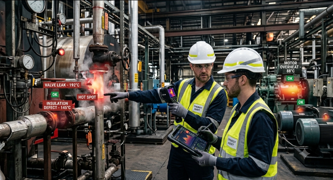
7. Fire Protection
Although modern batteries are much safer than earlier generations, fire protection remains essential.
A complete fire protection system typically includes:
- Smoke detectors
- Heat detectors
- Gas detection
- Thermal runaway detection
- Automatic fire suppression
- Emergency ventilation
Thermal Runaway Protection
Thermal runaway occurs when one battery cell overheats and triggers neighboring cells.
Protection measures include:
- Continuous temperature monitoring
- Early warning algorithms
- Module isolation
- Automatic shutdown
- Fire-resistant battery enclosures
- Ventilation systems
Early detection is critical to preventing large-scale incidents.
Communication Systems
Modern BESS installations rely heavily on communication networks.
Common protocols include:
- Modbus TCP
- Modbus RTU
- CAN Bus
- Ethernet/IP
- IEC 61850
- DNP3
These protocols enable communication between:
- BMS
- PCS
- EMS
- SCADA
- Utility control centers
Grid Protection Requirements
When connected to the electrical grid, BESS installations must comply with utility protection standards.
Typical protection functions include:
- Overvoltage
- Undervoltage
- Overfrequency
- Underfrequency
- Reverse power
- Anti-islanding protection
- Synchronization checks
- Differential protection
These protections ensure safe operation during grid disturbances.
Advantages of Proper BESS Protection Design
A well-designed protection system provides several benefits:
- Improved personnel safety
- Longer battery lifespan
- Higher system availability
- Reduced maintenance costs
- Better grid reliability
- Compliance with electrical standards
- Lower risk of equipment damage
Investing in comprehensive protection often reduces operational costs over the lifetime of the system.
Future Trends in Battery Energy Storage
Battery technology continues to evolve rapidly. Emerging trends include:
- Artificial intelligence for predictive maintenance
- Digital twin technology
- Solid-state batteries
- Sodium-ion battery systems
- Grid-forming inverters
- Cybersecurity for energy storage systems
- Faster fault detection using machine learning
These innovations aim to improve efficiency, safety, and resilience as energy storage becomes a larger part of modern power systems.
Conclusion
Battery Energy Storage Systems have become a cornerstone of modern electrical infrastructure. They help stabilize renewable energy generation, improve grid reliability, and support the transition toward cleaner power systems. However, achieving safe and dependable operation depends on more than battery capacity alone.
A successful BESS integrates robust electrical architecture with comprehensive protection systems, including advanced battery management, power conversion, thermal monitoring, fire protection, and intelligent control. As renewable energy deployment accelerates, well-engineered Battery Energy Storage Systems will continue to play a vital role in building a more reliable and sustainable electrical grid.
Frequently Asked Questions (FAQ)
What is a Battery Energy Storage System (BESS)?
A Battery Energy Storage System stores electrical energy and supplies it when demand increases or renewable generation decreases.
Why is a Battery Management System (BMS) important?
The BMS monitors battery health, balances cells, protects against overcharging and deep discharge, and enhances safety and battery lifespan.
What is the role of the Power Conversion System (PCS)?
The PCS converts direct current (DC) from the batteries into alternating current (AC) for the grid and converts AC back to DC during charging.
What are the main protection systems in a BESS?
Key protections include overcurrent, overvoltage, undervoltage, short-circuit, thermal, ground fault, fire suppression, and anti-islanding protection.
Which battery chemistry is most common in modern BESS installations?
Lithium Iron Phosphate (LFP) is widely used because it offers excellent safety, long cycle life, and strong thermal stability.